Objective 1.01: Explain, compare and contrast the OSI layers
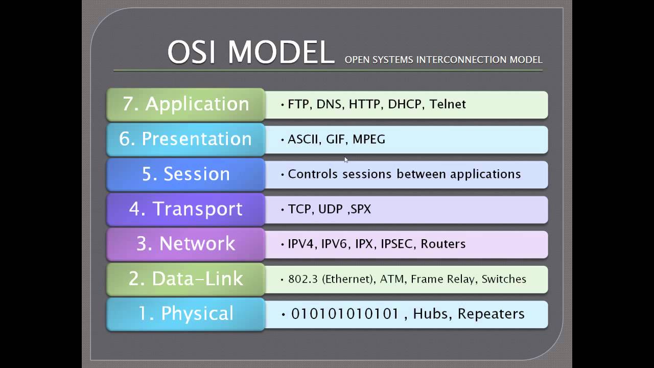
The OSI model is the general model used by most/all network solutions today. This model is composed of 7 layers: each layer has a specific role that sends and receives information to the layers directly above and below. This model allows for each layer to perform specific tasks and functions before passing traffic to the next layer.
Describe the function of each OSI layer / Differentiate between the OSI layers
- Physical: The physical layer describes the physical connection between devices, the types of cables or frequencies, voltage levels, adapters, and so on. In essence, the physical layer is all of the physical components (wired and wireless) in a network.
- Data Link: The data link layer is responsible for 2 things: addressing within the physical network and frame synchronization/error checking. Addressing uses Media Access Control, or MAC addresses – a 12 byte unique identifier that is a mixture of the manufacturer identity and a random number.
- Network: The network layer is responsible for addressing and routing on larger networks. The network layer is most commonly associated with an IP Address, but is responsible for much more. The network layer also performs packet sequencing, data fragmentation, creation of virtual circuits and more.
- Transport: The transport layer is responsible for flow control between multiple applications and services. This layer is commonly associated with TCP, and is responsible for confirming reliability of data transmission.
- Session: The session layer is responsible for creating, maintaining, and terminating conversations on the network. The easiest parallel to describe the session layer would be a telephone switchboard operator – they establish and maintain the connections between the parties, and then take down the connection when the conversation is finished.
- Presentation: The primary role of the presentation layer is to simply convert the well structured network data into something the application layer can understand, and visa-versa. This is necessary because applications may have many different ways to communicate, and this layer translates the communication methods into a single standard.
- Application: The application layer is the final layer of integration between the network and applications.
Describe the purpose of the various address types at different OSI layers
Traditionally, addressing occurs only at the Network and Data Link layers. The Data Link layer uses MAC addresses to identify and communicate with nodes over the Physical layer. This addressing method is inefficient as it requires broadcasts to find nodes and perform name resolution. NOTE: This will only allow communication with nodes that are on the same network.
The Network layer uses IP or IPX addresses to communicate with nodes that are potentially outside of the local network. These addresses are routable between networks and are therefore used as the backbone of the internet
Address Resolution Protocol, or ARP, is used to provide translation between Network and Data Link addresses.
More information:
OSI Model Wiki
Another OSI Model Overview
Objective 1.02: Explain protocols and technologies specific to the data link layer
The data link layer is often referred to as having 2 sublayers – the Media Access Control (MAC) layer, and the Logical Link Control (LLC) layer.
The MAC sublayer is responsible for:
- Frame delimiting and recognition
- Addressing of destination stations (both as individual stations and as groups of stations)
- Conveyance of source-station addressing information
- Transparent data transfer of LLC PDUs, or of equivalent information in the Ethernet sublayer
- Protection against errors, generally by means of generating and checking frame check sequences
- Control of access to the physical transmission medium
- receive/transmit normal frames
- half-duplex retransmission and backoff functions
- append/check FCS (frame check sequence)
- interframe gap enforcement
- discard malformed frames
- prepend(tx)/remove(rx) preamble, SFD (start frame delimiter), and padding
- half-duplex compatibility: append(tx)/remove(rx) MAC address
The LLC sublayer is responsible for providing enabling several network protocols (IP, IPX, Decnet, etc..) to coexist within a multipoint network and to be transported over the same network medium. It can also provide flow control and automatic repeat request (ARQ) error management mechanisms.
Explain the purpose of a switch’s forwarding database
A forwarding information base (FIB), also known as a forwarding table or CAM table, is most commonly used in network bridging, routing, and similar functions to find the proper interface to which the input interface should forward a packet. It is a dynamic table that maps MAC addresses to ports. It is the essential mechanism that separates network switches from network hubs.
An Ethernet switch’s role is to copy Ethernet frames from one port to another. The presence of a CAM table is one attribute that separates a switch from a hub. Without a functional CAM table, all frames received by a network switch would be echoed back out to all other ports, much like an Ethernet hub. A switch should only emit a frame on the port where the destination network device resides (unicast), unless the frame is for all nodes on the switch (broadcast) or multiple nodes (multicast).
Generally, the CAM table is a system memory construct used by Ethernet switch logic to map a station’s MAC address to the switch port the station is connected to. This allows switches to facilitate communications between connected stations at high speed regardless of how many devices are connected to the switch. The CAM table is consulted to make the frame forwarding decision. Switches learn MAC addresses from the source address of Ethernet frames on the ports, such as Address Resolution Protocol response packets.
Explain the purpose and functionality of ARP
ARP is used for converting a network address (e.g. an IPv4 address) to a physical address like an Ethernet address (also named a MAC address). ARP has been implemented with many combinations of network and data link layer technologies, like IPv4, Chaosnet, DECnet and Xerox PARC Universal Packet (PUP) using IEEE 802 standards, FDDI, X.25, Frame Relay and Asynchronous Transfer Mode (ATM). IPv4 over IEEE 802.3 and IEEE 802.11 is the most common case.
In Internet Protocol Version 6 (IPv6) networks, the functionality of ARP is provided by the Neighbor Discovery Protocol (NDP).
The Address Resolution Protocol is a request and reply protocol that runs encapsulated by the line protocol.[clarification needed] It is communicated within the boundaries of a single network, never routed across internetwork nodes. This property places ARP into the Link Layer of the Internet Protocol Suite,[2] while in the Open Systems Interconnection (OSI) model, it is often described as residing between Layers 2 and 3, being encapsulated by Layer 2 protocols. However, ARP was not developed in the OSI framework.
Explain the purpose and functionality of MAC addresses
A media access control address (MAC address) is a unique identifier assigned to network interfaces for communications on the physical network segment. MAC addresses are used as a network address for most IEEE 802 network technologies, including Ethernet and WiFi. Logically, MAC addresses are used in the media access control protocol sublayer of the OSI reference model.
MAC addresses are most often assigned by the manufacturer of a network interface controller (NIC) and are stored in its hardware, such as the card’s read-only memory or some other firmware mechanism. If assigned by the manufacturer, a MAC address usually encodes the manufacturer’s registered identification number and may be referred to as the burned-in address (BIA). It may also be known as an Ethernet hardware address (EHA), hardware address or physical address. This can be contrasted to a programmed address, where the host device issues commands to the NIC to use an arbitrary address.
A network node may have multiple NICs and each NIC must have a unique MAC address.
Explain the purpose and functionality of a broadcast domain
A broadcast domain is a logical division of a computer network, in which all nodes can reach each other by broadcast at the data link layer. A broadcast domain can be within the same LAN segment or it can be bridged to other LAN segments.
In terms of current popular technologies: Any computer connected to the same Ethernet repeater or switch is a member of the same broadcast domain. Further, any computer connected to the same set of inter-connected switches/repeaters is a member of the same broadcast domain. Routers and other higher-layer devices form boundaries between broadcast domains.
This is as compared to a collision domain, which would be all nodes on the same set inter-connected repeaters, divided by switches and learning bridges. Collision domains are generally smaller than, and contained within, broadcast domains.
While some layer two network devices are able to divide the collision domains, broadcast domains are only divided by layer 3 network devices such as routers or layer 3 switches. Separating VLANs divides broadcast domains as well, but provides no means to network these without layer 3 functionality.
Explain the purpose and functionality of VLANs
A virtual LAN (VLAN) is any broadcast domain that is partitioned and isolated in a computer network at the data link layer (OSI layer 2).[1][2] LAN is an abbreviation of local area network.
To subdivide a network into virtual LANs, one configures a network switch or router. Simpler network devices can only partition per physical port (if at all), in which case each VLAN is connected with a dedicated network cable (and VLAN connectivity is limited by the number of hardware ports available). More sophisticated devices can mark packets through tagging, so that a single interconnect (trunk) may be used to transport data for multiple VLANs. Since VLANs share bandwidth, a VLAN trunk might use link aggregation and/or quality of service prioritization to route data efficiently.
VLANs allow network administrators to group hosts together even if the hosts are not on the same network switch. This can greatly simplify network design and deployment, because VLAN membership can be configured through software. Without VLANs, grouping hosts according to their resource needs necessitates the labour of relocating nodes and/or rewiring data links.
Explain the purpose and functionality of link aggregation
Yhe term link aggregation applies to various methods of combining (aggregating) multiple network connections in parallel in order to increase throughput beyond what a single connection could sustain, and to provide redundancy in case one of the links should fail.
Further umbrella terms used to describe the method include port trunking,[1]link bundling,[2] Ethernet/network/NIC bonding,[1] or NIC teaming. These umbrella terms encompass not only vendor-independent standards such as Link Aggregation Control Protocol (LACP) for Ethernet defined in IEEE 802.1AX and IEEE 802.1aq or the previous IEEE 802.3ad, but also various proprietary solutions.
More Information:
ARP
ARP on F5
MAC Address
Media Access Control
Logical Link Control
CAM Table
Broadcast Domain
VLANs
Link Aggregation Wiki
Big IP Link Aggregation
Objective 1.03: Explain protocols and apply technologies specific to the network layer
The network layer provides the functional and procedural means of transferring variable length data sequences (called datagrams) from one node to another connected to the same network. It translates logical network address into physical machine address. A network is a medium to which many nodes can be connected, on which every node has an address and which permits nodes connected to it to transfer messages to other nodes connected to it by merely providing the content of a message and the address of the destination node and letting the network find the way to deliver (“route”) the message to the destination node. In addition to message routing, the network may (or may not) implement message delivery by splitting the message into several fragments, delivering each fragment by a separate route and reassembling the fragments, report delivery errors, etc.
Datagram delivery at the network layer is not guaranteed to be reliable.
A number of layer-management protocols belong to the network layer. These include routing protocols, multicast group management, network-layer information and error, and network-layer address assignment.
Explain the purpose and functionality of IP addressing and subnetting
The success of TCP/IP as the network protocol of the Internet is largely because of its ability to connect together networks of different sizes and systems of different types. These networks are arbitrarily defined into three main classes (along with a few others) that have predefined sizes, each of which can be divided into smaller subnetworks by system administrators. A subnet mask is used to divide an IP address into two parts. One part identifies the host (computer), the other part identifies the network to which it belongs.
Given an IP address and net mask, determine the network IP and the broadcast IP
|
Hosts |
Netmask |
Number of Subnets |
| /30 |
4 |
255.255.255.252 |
64 |
| /29 |
8 |
255.255.255.248 |
32 |
| /28 |
16 |
255.255.255.240 |
16 |
| /27 |
32 |
255.255.255.224 |
8 |
| /26 |
64 |
255.255.255.192 |
4 |
| /25 |
128 |
255.255.255.128 |
2 |
| /24 |
256 |
255.255.255.0 |
1 |
| /23 |
512 |
255.255.254.0 |
2 |
| /22 |
1024 |
255.255.252.0 |
4 |
| /21 |
2048 |
255.255.248.0 |
8 |
| /20 |
4096 |
255.255.240.0 |
16 |
| /19 |
8192 |
255.255.224.0 |
32 |
| /18 |
16384 |
255.255.192.0 |
64 |
| /17 |
32768 |
255.255.128.0 |
128 |
| /16 |
65536 |
255.255.0.0 |
256 |
Given a routing table and a destination IP address, identify which routing table entry the destination IP address will match
In computer networking a routing table, or routing information base (RIB), is a data table stored in a router or a networked computer that lists the routes to particular network destinations, and in some cases, metrics (distances) associated with those routes. The routing table contains information about the topology of the network immediately around it. The construction of routing tables is the primary goal of routing protocols. Static routes are entries made in a routing table by non-automatic means and which are fixed rather than being the result of some network topology “discovery” procedure
Shown below is an example of what the table above could look like on an average computer connected to the internet via a home router:
| Network Destination |
Netmask |
Gateway |
Interface |
Metric |
| 0.0.0.0 |
0.0.0.0 |
192.168.0.1 |
192.168.0.100 |
10 |
| 127.0.0.0 |
255.0.0.0 |
127.0.0.1 |
127.0.0.1 |
1 |
| 192.168.0.0 |
255.255.255.0 |
192.168.0.100 |
192.168.0.100 |
10 |
| 192.168.0.100 |
255.255.255.255 |
127.0.0.1 |
127.0.0.1 |
10 |
| 192.168.0.1 |
255.255.255.255 |
192.168.0.100 |
192.168.0.100 |
10 |
- The column Network Destination and Netmask together describe the Network id as mentioned earlier. For example, destination 192.168.0.0 and netmask 255.255.255.0 can be written as network id 192.168.0.0/24.
- The Gateway column contains the same information as the Next hop, i.e. it points to the gateway through which the network can be reached.
- The Interface indicates what locally available interface is responsible for reaching the gateway. In this example, gateway 192.168.0.1 (the internet router) can be reached through the local network card with address 192.168.0.100.
- Finally, the Metric indicates the associated cost of using the indicated route. This is useful for determining the efficiency of a certain route from two points in a network. In this example, it is more efficient to communicate with the computer itself through the use of address 127.0.0.1 (called “localhost”) than it would be through 192.168.0.100 (the IP address of the local network card).
Explain the purpose and functionality of Routing protocols
A routing protocol specifies how routers communicate with each other, disseminating information that enables them to select routes between any two nodes on a computer network. Routing algorithms determine the specific choice of route. Each router has a priori knowledge only of networks attached to it directly. A routing protocol shares this information first among immediate neighbors, and then throughout the network. This way, routers gain knowledge of the topology of the network.
Although there are many types of routing protocols, three major classes are in widespread use on IP networks:
- Interior gateway protocols type 1, link-state routing protocols, such as OSPF and IS-IS
- Interior gateway protocols type 2, distance-vector routing protocols, such as Routing Information Protocol, RIPv2, IGRP.
- Exterior gateway protocols are routing protocols used on the Internet for exchanging routing information between Autonomous Systems, such as Border Gateway Protocol (BGP), Path Vector Routing Protocol.
Explain the purpose of fragmentation
In a case where a router receives a protocol data unit (PDU) larger than the next hop’s MTU, it has two options if the transport is IPv4: drop the PDU and send an Internet Control Message Protocol (ICMP) message which indicates the condition Packet too Big, or fragment the IP packet and send it over the link with a smaller MTU.
If a receiving host receives a fragmented IP packet, it has to reassemble the datagram and pass it to the higher protocol layer. Reassembly is intended to happen in the receiving host but in practice it may be done by an intermediate router, for example, network address translation (NAT) may need to re-assemble fragments in order to translate data streams, description provided in RFC 2993.
IP fragmentation can cause excessive retransmissions when fragments encounter packet loss and reliable protocols such as TCP must retransmit all of the fragments in order to recover from the loss of a single fragment. Thus, senders typically use two approaches to decide the size of IP datagrams to send over the network. The first is for the sending host to send an IP datagram of size equal to the MTU of the first hop of the source destination pair. The second is to run the path MTU discovery algorithm, described in RFC 1191, to determine the path MTU between two IP hosts, so that IP fragmentation can be avoided.
NOTE: IPv6 hosts are required to determine the optimal Path MTU before sending packets; however, it is guaranteed that any IPv6 packet smaller than or equal to 1280 bytes must be deliverable without the need to use IPv6 fragmentation.
Given a fragment, identify what information is needed for reassembly
The Identification field, and Fragment offset field along with Don’t Fragment and More Fragment flags in the IP protocol header are used for fragmentation and reassembly of IP datagrams.
Explain the purpose of TTL functionality
The time-to-live value can be thought of as an upper bound on the time that an IP datagram can exist in an Internet system. The TTL field is set by the sender of the datagram, and reduced by every router on the route to its destination. If the TTL field reaches zero before the datagram arrives at its destination, then the datagram is discarded and an ICMP error datagram (11 – Time Exceeded) is sent back to the sender. The purpose of the TTL field is to avoid a situation in which an undeliverable datagram keeps circulating on an Internet system, and such a system eventually becoming swamped by such “immortals”.
In theory, under IPv4, time to live is measured in seconds, although every host that passes the datagram must reduce the TTL by at least one unit. In practice, the TTL field is reduced by one on every hop. To reflect this practice, the field is renamed hop limit in IPv6.
Given a packet traversing a topology, document the source/destination IP address/MAC address changes at each hop
Assuming there is no NAT, PAT, or proxies in use, the source and destination IP addresses will not change as a packet traverses a topology. The MAC addresses, however, are changed with every layer 3 device.
If the source/destination are within the same broadcast domain, the two systems will communicate directly, without changing of the MAC addresses. However, if they devices are not within the same broadcast domain, a layer 3 device must route between the networks.
- The sending device sends data to the MAC address of the layer 3 device
- Using IP addressing, the layer 3 device determines the next hop.
- Using its own MAC as the source, and the next hop MAC address as the target, the layer 3 device sends the data out the next interface
- This repeats until the next hop device is the intended target
More Information:
Routing on F5
TCP/IP Overview
IP Addressing & Subnetting
Routing Protocols
IP Packet Fragmentation
IP TTL (Time to Live)
Subnetting study guide
Routing Table
Objective 1.04: Explain the features and functionality of protocols and technologies specific to the transport layer
The transport layer controls the reliability of a given link through flow control, segmentation/desegmentation, and error control. Some protocols are state- and connection-oriented. This means that the transport layer can keep track of the segments and retransmit those that fail. The transport layer also provides the acknowledgement of the successful data transmission and sends the next data if no errors occurred. The transport layer creates packets out of the message received from the application layer. Packetizing is a process of dividing the long message into smaller messages.
Compare/Contrast purpose and functionality of MTU and MSS
The Maximum Transmission Unit (MTU) operates on Layer 3 (Network Layer) and defines how large a packet can be. Any larger that this value, and the packet is fragmented, or split into 2 or more packets.
The Maximum Session Size (MSS) operates on Layer 4 (Transport Layer) and is almost always 40 bytes less than the MTU. If the packet is larger than the MSS, the packet is rejected and has to be recreated.
Explain the purpose and functionality of TCP
Connection oriented, guaranteed delivery, requires additional overhead
Explain the purpose and functionality of UDP
Not connection oriented, not guaranteed deliver, less overhead than TCP
Explain the purpose and functionality of ports in general
A port is an endpoint that is normally associated with a service. This allows an IP address to provide multiple services at the same time. https://en.wikipedia.org/wiki/Port_(computer_networking)
Explain how retransmissions occur
Retransmissions occur when the recieving computer alerts the sending computer of corrupt or missing data. This is normally associated with TCP and relies on the guaranteed delivery features such as packet IDs, sequence numbers, and error checking.
Explain the purpose and process of a reset
A reset is generated whenever something “unexpected” occurs. This can be caused by corrupt packets, invalid sequence numbers, receiving data from a client that doesnt have an active connection, etc…
The reset flag is used to “reset” or abort a connection.
Describe various TCP options
The TCP header is composed of several settings and options that describe the packet and how to handle the information enclosed. Header options include the following:
- Source Port: 16 bits
- Destination Port: 16 bits
- Sequence Number: 32 bits
- Acknowledgment Number: 32 bits
- Data Offset: 4 bits
- Reserved: 6 bits
- Control Bits: 6 bits (from left to right):
- URG: Urgent Pointer field significant
- ACK: Acknowledgment field significant
- PSH: Push Function
- RST: Reset the connection
- SYN: Synchronize sequence numbers
- FIN: No more data from sender
- Window: 16 bits
- Checksum: 16 bits
- Urgent Pointer: 16 bits
- Options: variable
- End of Option List
- No-Operation
- Maximum Segment Size
- Padding: variable
Describe a TCP checksum error
As part of the guaranteed delivery in TCP, a checksum is generated with each packet. This checksum is used to validate if the data within the packet is corrupted. In most environments, checksum errors should be very rare.
Describe how TCP addresses error correction
Similar to the checksum eror above, TCP uses error detection to request retransmission of error packets. This occurs from both the client requesting a resend of bad packets, as well as the server confirming the receipt of sent pacckets
Describe how the flow control process occurs
At the beginning of a TCP header, there is a field called the Advertized Window Size. This window size states the maximum amount of data that one computer should send to the other. The window size is normally related directly to the size of the receive buffer. As long as the sending computer honors the window size, the s.ystems will never be overwhelmed
More Information:
MSS
TCP Functionality
TCP Connection Setup by Virtual Server Type
TCP Profile Settings (Tunables)
UDP Functionality
UDP Profile Settings (Tunables)
TCPDUMP on F5
TCP Header Format
Objective 1.05: Explain the features and functionality of protocols and technologies specific to the application layer
Explain the purpose and functionality of HTTP
The Hyper Text Transfer Protocol operates at layer 7 (application), and defines a structured text method for distributed information systems. HTTP is the basis for much of the internet and is interpreted by web browsers. More information can be found at https://en.wikipedia.org/wiki/Hypertext_Transfer_Protocol
Differentiate between HTTP versions
HTTP originally started with version 0.9, who’s key identifier was that it consisted solely of the GET method.
HTTP 1.0 has been the most popular HTTP implementation to date and is composed of several loosely defined standards. The main drawback of HTTP 1.0 wasn’t strictly defined, leaving leeway between how browsers and servers interpreted different commands.
HTTP 1.1 came about to improve on 1.0. The schema was well defined and therefore resulted in similarity between vendor solutions. Additionally, new error codes were provided (24 instead of the previous 16), additional authentication methods, and better handling of TCP connections.
Interpret HTTP status codes
There are several common error codes, such as 301 Moved Permanently, 404 Not Found, and 503 Service Unavailable. These are seen frequently and are easy to get to know. However, the error codes are also grouped by the 100’s for similar error types:
1xx – Informational
2xx – Successful
3xx – Redirection
4xx – Client Error
5xx – Server Error
Determine an HTTP request method for a given use case
There are several HTTP request methods: GET, POST, HEAD, PUT, DELETE, OPTIONS, CONNECT. The first two: GET and POST are the most commonly used. The primary difference between the two methods are how they request information.
GET requests information by placing variables in the URL, often seen as form.html?name1=value1&name2=value2. The benefit of this method is that it is easy to see the data being transmitted, and the target location can be bookmarked for future reference. The drawback of this method however is the limited length of the URL and difficulty handling non-text data types.
POST requests information by submitting data to the server. This has several benefits including keeping the URL clean, restricting bookmarks, allowing for unlimited data size, and even obscuring the data being transmitted.
Explain the purpose and functionality of HTTP keepalives, HTTP headers, DNS, SIP, FTP
Differentiate between passive and active FTP
Active and passive FTP refer to how the FTP connections are constructed. FTP uses 2 connections: a command and a data connection. The difference between these two methods is how, and by whom, the data connection is established.
For an Active FTP session, the client starts by initiating the command connection to port 21 on the server. The server then initiates the data connection to the client using a port greater than 1024. If the client is behind a firewall, this can result in a failed connection
For a Passive FTP session, the client also starts by initiating the command connection to port 21 on the server. The server then responds with a port greater than 1024, which the client then uses to initiate the data connection. Because both connections are generated by the client, its position behind a firewall is not a problem.
Explain the purpose and functionality of SMTP
Simple Mail Transfer Protocol (SMTP) is a standard used for transferring email over the internet using TCP port 25.
Explain the purpose and functionality of a cookie
A cookie is a small file (physical or in memory) on a client computer that is sent to a website whenever the user browses that site. This file can contain simple identifiable information such as an ID, or complex information such as credit cards and passwords.
Initially, cookies were designed to assist with maintaining user sessions and preferences when visiting sites. Recently, cookies have come under suspicion because of their use by advertisers and the ability to track users across multiple web sites. https://en.wikipedia.org/wiki/HTTP_cookie
Given a situation in which a client connects to a remote host, explain how the name resolution process occurs
Name resolution is performed using the Domain Naming System (DNS) services. DNS is structured in a hierarchical manner, normally read from right to left. For instance, in the host blog.edgoad.com:
- First, your client contacts your local DNS, or LDNS and requests the host blog.edgoad.com
- Next, your LDNS contacts the root DNS servers requesting the location of the COM DNS servers.
- Once the addresses for the COM servers have been received, your LDNS then asks the COM DNS servers for the address of the EDGOAD DNS servers.
- Once the addresses for the EDGOAD servers have been received, your LDNS then asks the EDGOAD DNS servers for the address of the BLOG servers.
- Finally, your LDNS has fully traversed the DNS infrastructure to associate the DNS name with an IP address, which is returned to your client
Explain the purpose and functionality of a URL
A URL is used to specify the location of a resource on a network, and the method of retrieving it. A URL is composed of the following 5 items.
- The protocol / scheme to use (http, https, ftp, etc…)
- A colon and 2 forward slashes
- A host name or IP address
- Optionally, a colon followed by port number
- The full path of the resource
- The protocol is: HTTP
- The host name is: blog.edgoad.com
- The full path of the resource is: /2015/02/configuring-vnc-to-auto-start-rhel-62.html
HTTP Functionality
HTTP Status Codes
HTTP Headers
F5 HTTP White Paper
DNS Functionality
DNS Record Types
SIP Functionality
F5 SIP White Paper
FTP Functionality
SMTP Functionality
HTTP Cookies
My Name is URL